


We were asked to develop a safety library for use with Rockwell architecture, expanding on existing Rockwell safety Add On Instructions (AOIs) to provide annunciation of faults and statuses using tag based alarms for a MagneMotion based system.
In line with best practice and ISO standards, our safety library has to follow the V-Model.
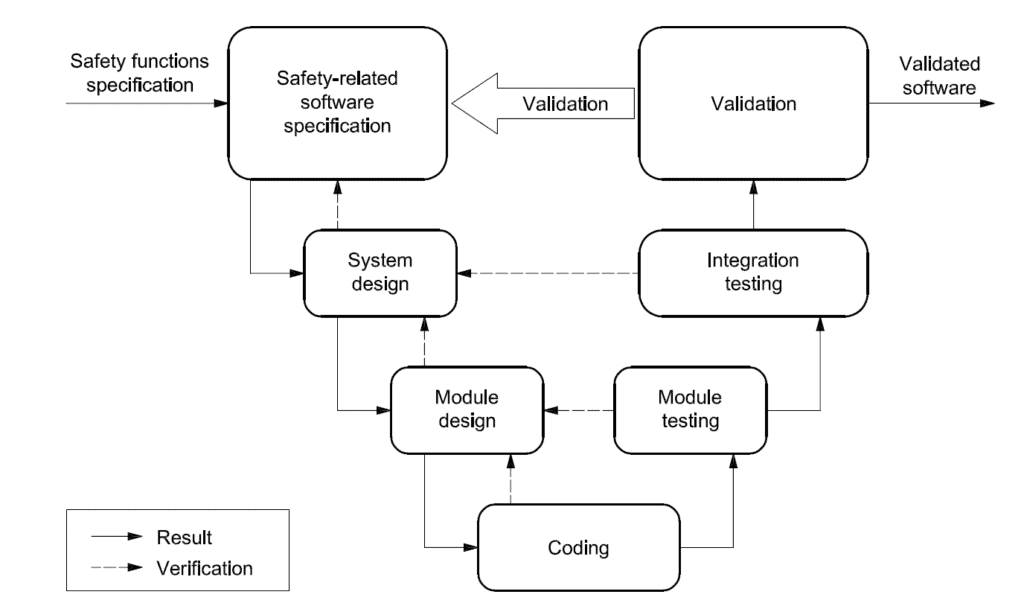
For SRASW for components with PLr from a to e, the following basic measures shall be applied:
— development lifecycle with verification and validation activities
— documentation of specification and design;
— modular and structured programming;
— functional testing;
— appropriate development activities after modifications.
Development Lifecycle and Documentation
As a Rockwell Automation Systems Integrator, we adhere to the Rockwell quality assurance system; which covers the development lifecycle and documentation activities.
This includes peer verification and validation activities plus fully documented AOIs which allow further development activity in the future. This addressed the Client’s intention to periodically modify the system, which will inevitably require future modifications to the safety software to ensure the Client’s modifications are rendered safe.
Modular and Structured Programming
All programming is designed using modular principles based on User Defined Data Types (UDTs) and Add On Instructions (AOIs). AOIs (Add on Instructions) were chosen because:
- The safety library was to be used as part of a modular mechanical, electrical and software application – we therefore interpreted this to include the safety software.
- AOIs are appropriate to the V Model
- AOIs feature a dated signature and id function that dovetails into any audit system.
Functional Testing
We developed a suite of simulation tools, which combine with the simulation function inherent to MagneMotion, to enable both the module testing and integration testing of the V Model. This allows for virtual commissioning of the complete project, including the safety functions.
To enable this, we included a method in the I/O function block monitors, to enable a future engineering team to evaluate in simulation any proposed modifications to the system and make their own evaluation of the risk presented by their activities and reduce the associated risks of modifying an unfamiliar system in situ.
As such the simulation tools had to be designed to be retained in both the I/O module blocks and the general application AOI suite for the whole lifetime of the machine, “cradle to grave”. This assists the employer to meet the requirements of the Provision and Use of Work Equipment Regulations 1998:
(1) Every employer shall ensure that, where appropriate, work equipment is provided with one or more controls for the purposes of …
Regulation 14(1)(b)
..(b) controlling any change in the […] operating conditions of the work equipment where such conditions after the change result in risk to health and safety which is greater than or of a different nature from such risks before the change.
As per ISO 13849-1, these tools also ensure not only appropriate development activities during the initial coding of the software, but following any future modifications.
Required Performance Level
The library was designed to meet the a performance level required of PL=d. This performance level required control and data flow analysis, as per the relevant standards.
The use of a GuardLogix PLC allows for reaction times to be easily evaluated. However, in this instance not only were reaction times for the PLC and isolating contactors required to be taken into account, but the nature of MagneMotion meant that mathematical calculations had to take into account acceleration and deceleration curves plus the maximum speed.
Building on Standard Routines
Whilst the libraries were new for this job, we based them on existing libraries; reduced and simplified to bring in line with modern software approaches:
- Removing redundant features no longer supported in the Rockwell product, such as server based alarms
- Allowing for further improved diagnostics leveraging the power of tag based alarms
- Meeting the Client’s requirements for Rockwell to provide auditable data for their use.
Further, by using AOIs with auditing facilities to encapsulate control functions and prohibiting any code outside the AOI save for run chains of XIC failsafe contacts driving a single OTE enable contact, this enforces the requirement to guide the developer because the Client or any other interested party can easily identify an offending link in the safety software.
Unfortunately, the Standard does not offer any guidance for an item to be deleted out of the run chain, however, from experience, people do not delete code, they link around code. Nevertheless, if this should occur, the change should be captured by the overall safety signature for the PLC changing.
Self-Diagnostic Sequencers
With the client being in the automotive industry, as such, the de facto software vernacular is the use of Self-Diagnostic Sequencers (SDS). This has the following merits:
- Presents a semi-formal method of coding sequential problems.
- Allows a problem to be broken up into discrete steps, so that each step can be handled correctly in a specific order, thereby allowing straight forward functional testing of more complex safety functions, thus avoiding the ambiguous interpretation of freeform logic.
- Allows annunciation on a HMI or equivalent, of each function step which has benefits at the module testing, integration and validation stages. It also provides diagnostic benefits for the client when going forward with operation and maintenance of the installation.
- Readily understood by other programmers within the automotive industry.
The sequencers comply with the requisite legal standards in that they do not manipulate the program flow and contain no jump instructions or calculated addresses that could be used to modify a program counter.
Our Approach
The basic philosophy to our safety library is:
- Where available, use Rockwell proprietary safety instructions as these instructions are independently TUV validated functions.
- “Wrap up” any proprietary instruction inside an AOI where the fault and diagnostic data is exposed in a standard way.
- AOI audit information can be used to ensure traceability.
The library AOIs are designed to meet the following programming rules which are in line with Annex J of the Standard. Each AOI has one entry and one exit point.
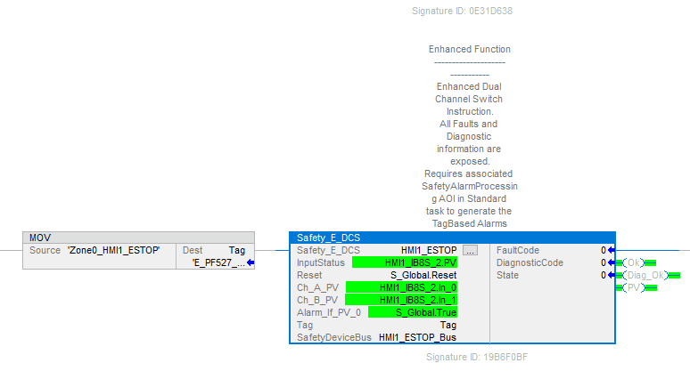
There are four types of AOI:
Wrap Up AOI
An enhanced proprietary function block, using the naming convention Safety_E _function.
The structure:
- A standard header to pass Enable In / Enable Out and Reset Function
- Call the proprietary instruction (eg, DCS) and name it Local_Device and use the standard OK and diag_OK rung
- Map the Local_Device outputs to PV and any other outputs
- Use a standard SafetyDeviceStateCondition footer
Multiple Function AOI
Reliant on more than one proprietary function block, using the naming convention Safety_M_function. Embed the the required validated Safety_E_function blocks and associated logic to enable the safety function to be achieved, preserving the validation provenance; the enhanced fault and diagnostics annunciation; and the modular characteristics.
A sequencer may be required to handle any specific logic within the AOI which controls the Safety_E_function blocks.
The structure:
- A standard header to pass Enable In / Enable Out and Reset Function
- Use validated function blocks necessary to the safety functionality
- If necessary, add a sequencer for handling the calls to and outputs from the validation function blocks.
- Any specific logic for handling timers or sounders / lights is added
- Use a standard SafetyDeviceStateCondition footer
- Any final safety function specific annunciation is placed at the end
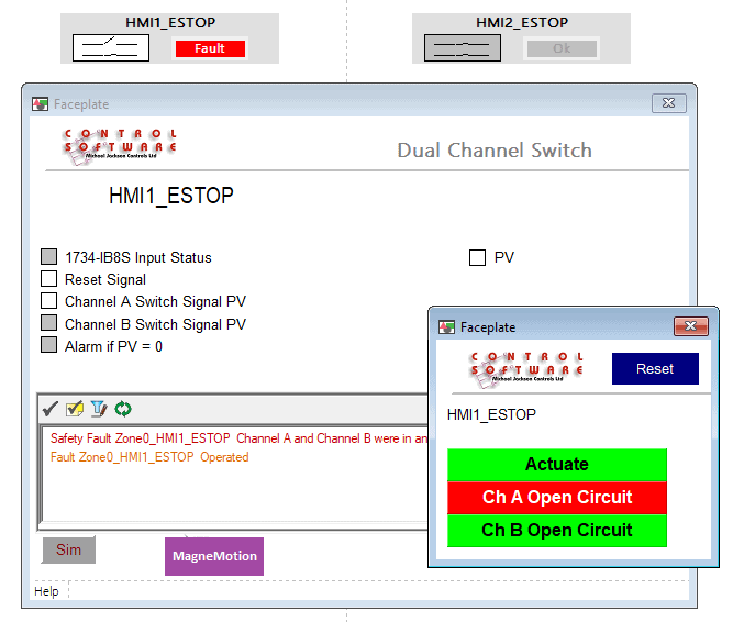
The use of suitable filters and naming conventions on all instances of the Safety_M_Function and embedded Safety_E_Functions will enable the standard FTview Alarm viewer to show all necessary faults and diagnostic messages.
Custom AOI
Used where there is no proprietary function available to achieve the required safety function.
If a sequencer is appropriate, as for the automotive industry, this is the first choice; otherwise, it is a logic problem that invariably contains an OR (which is a muting function in line with 5.2.5 of the Standard).
Where it is a muting problem, there is a responsibility to ensure that the provision of the Standard “…safe conditions shall be provided by other means” is met. Therefore, by encapsulating the muting function inside an AOI, this allows the input for the safe conditions provided by other means to be explicitly named SafetyOtherMeans with a comment referencing 5.2.5 thereby drawing attention to this provision. Moreover, it is prohibited to code an OR outside of the AOI even if they are both safety signals as this allows easy identification of alien code as it should not be there (these branches are assumed to be links equivalent to a physical shorting link wire).
This uses the naming convention Safety_C _function.
The structure:
- A standard header to pass Enable In / Enable Out and Reset Function
- Any specific logic for handling the safety function
- Use a standard SafetyDeviceStateCondition footer
I/O Module AOI
Used to monitor the health of an I/O module to provide any diagnostics related to the communications and inhibit outputs if a problem is detected. This allows for off-site simulation.
This uses the naming convention Safety_MOD _PartId.
The structure is semi-formal, but mostly adheres to the following rules:
- A standard header to pass Enable In / Enable Out; Simulation / Simulation Mode and Reset
- Process any inputs (or simulated inputs) and map into a logical input, such as In_0. Keep branches to a maximum of 4 on a rung to keep it manageable
- Process any module system information (typically Run Mode or Connection Faulted)
- Process any module specific inputs (such as muting)
- If appropriate, outputs can be marshalled through the AOI where consideration of the inputs status is required, for example in Safety_MOD_PF527, the output (SafeTorqueOff) needs to be disabled if there is an issue with communication with the card
- If required, add a rung to reset the Module
- Create a run chain to drive the PV, OK and Diag_OK signals (PV and Diag_OK are maintained for consistency across the library). Unlike a proprietary instruction, the I/O image structure for Rockwell I/O device does not contain any fault or diagnostic codes
- Map the tag name to the SafetyDeviceBus and create any custom module code errors
- Use a standard SafetyDeviceStateCondition footer
Counter-intuitively, an AOI which monitors a safety output card module, actually acts as an input module monitor (it monitors the readback), communication status etc following the above structure.
Safety Related Functions
A suite of Safety Related Functions in the Standard Area which are used for dealing with the actual diagnostic information and messages from the various Safety AOIs. These user the naming convention Safety_SRF_function.
Architecture Model
As discussed above, the library adheres to the General Architecture Model of Software as per the Standard. Typically:
- The input circuit will be a dual channel circuit monitoring one device.
- The Input Module condition is monitored to ensure that the signals are real
- All Sensors are then processed within the dedicated AOIs
- Physically, the GuardLogix PLC is the processing block. Further, the software structure includes AOIs for individual functional safety logic processing.
- The Output Module condition is monitored to ensure that the signals are real
- Output actuators eg. relays or safe torque off signals, are processed by dedicated AOIs.
- The output circuits comply with the hardware requirements of the Standard
All outputs have unique addresses and are enabled at only one program location.
Defensive Programming
As stated, the library includes AOIs which monitor the I/O modules and the proprietary instructions are designed to look at discrepancy errors etc. Where set points are passed into an AOI as a parameter, checks are performed within the AOI to ensure that they fall within set limits as a sanity check. However, the correct values must be set according risk assessment based on actual hardware being fitted.
GuardLogix PLCs are split into unambiguous Safety and Standard Areas. Further, there is only one very rigidly defined route to pass data from the Standard Area to the Safety Area (Safety and Tag Mapping Dialog). We prefix it as From_Standard_tag. General data, eg reset buttons, astables (1 second flash) etc, is represented in a single UDT (udt_Standard_To_Safety) and addressed as App_Global in the standard task and S_Global in the safety task.
Further, simulation data is passed as SIM_tag_Standard and received in the safety task as SIM_tag_Safety where tag is the respective device id.
Simulation
Simulation is at the heart of our software design. It is a fundamental tenet of best practice software development that all software is tested under simulation and only progressing to a live system once a very high confidence in the ability of the code to perform its required duty is achieved.
As such, this library features a full set of simulation validation tools that firstly allow testing with the host PLC thereby negating the need to acquire or purchase expensive test equipment and secondly provide a means of demonstrating all safety functions to any interested party prior to attending site.
Although simulation uses an OR of a non-safety-related signal (simulation), this can be distinguished because:
- Simulation is ONLY included to meet the simulation requirements of the Standard
- When deployed, the first line of the main safety routine features a hard-coded unlatch simulation bit
- If the Safety_MOD_Function detects a RunMode input from the physical device, it disables the OK output from the AOI, effectively disabling all safety outputs for the contactors.
- It is impossible to change that hard-coded command after validation without entering the safety task password and associated checksums will change.
Due to the validation process (V-Model) it is difficult to see how to remove any simulation code after validation as this requires a code change that then has to be re-validated without simulation code.
Control and Data Flow Analysis
This is required in the case of any of Custom AOIs where the program flow needs to be tested in order to ensure that all rungs are evaluated. The Module Design Specification for the Custom AOIs includes a program flow chart and testing approach. Other AOI types simply add diagnostics to proprietary instructions.